Be Our Guest: Optical Voltage Transducers for High-Voltage Applications

Editor's note: This paper was originally presented at an EPRI conference by F. Rahmatian, D. Romalo, S. Lee, A. Fekete, and S. Liu of NxtPhase and N.A.F. Jaeger and P. Chavez of the University of British Columbia. Power Online has permission to use the paper in its entirety. For more on the sensor technologies developed by NxtPhase, see Be Our Guest: Optical Current Transducers for High Voltage Applications, 3-10. ACM
Optical methods for the measurement of current and voltage in high-voltage (HV) environments have been attracting more and more attention in recent years. This is mostly due to the advantages that they offer over conventional instrument transformers. They provide immunity to electromagnetic interference, are typically non-intrusive, provide excellent galvanic isolation, are much lighter and, therefore, easier to transport and install.
Early work on optical current and voltage sensing in the HV environment started in the 1970s [1-5] leading to more practical and accurate systems developed in the 1980s and 1990s [6-13]. Also, at the commercial level, current sensing technology (both for technical and economical reasons) led voltage sensing technology. In this paper, we present results obtained using NxtPhase's optical voltage transducer, NXVT.
Most practical optical voltage sensors use electric field sensors that operate using the linear electro-optic (or Pockels) effect. It should be noted that the sensors themselves are, strictly speaking, electric field sensors and not voltage sensors. However, various means of getting a one-to-one relationship between the voltage applied and the electric field sensed are used to derive voltage. For example, the entire voltage can be applied across the electro-optic crystal, or a capacitive divider can be used to apply a well-known fraction of the voltage to be measured across optical electric field sensors.
There are advantages and disadvantages to each of these methods. Nevertheless, most successful devices in the past have used optical fibers for the transmission of light, bulk electric field sensors as sensing elements, and SF6 gas for insulation.
The NXVT introduced here combines the typical benefits of optical sensing technology with some additional features that provide further benefits to the user. For example, it does not use SF6 or oil-paper insulation, making it more environmentally friendly and much safer to use. The NXVT uses multiple miniature electric field sensors inside a high-quality post insulator, in a proprietary manner, to measure voltage with high accuracy. We will describe the NXVT and present the results of some HV tests to demonstrate its operating principle.
The NXVT uses a proprietary method of measuring electric fields at several points and dynamically combining the results to obtain the voltage difference across its terminals. It consists of a hollow HV insulator with miniature electric field sensors mounted inside the insulator column. The location of the electric field sensors inside the column and the mathematical function combining the measurements to obtain voltage are both determined so that changes in the environment and other phases of a three-phase system, namely external influences, will not affect the voltage measured.
Electric fields measured can change substantially due to these external influences; nevertheless, the way in which the measurements are combined and the positioning of the electric field sensors results in a voltage measurement that is virtually insensitive to these influences.
After a great deal of numerical modeling, a prototype 230 kV class NXVT was fabricated and tested to prove the concept. It consisted of a high-quality 2.3m polymer insulator with metallic electrodes and flanges at its two ends and housing three electric field sensors. (See Figures 1, 2, and 3.) The electric field sensors used were integrated optics Pockels cells (IOPC) [14, 15]. The IOPCs were located at specific locations inside the column, one near the top, one close to the middle, and the third close to the bottom of the column. The insulator column was filled with air.
The transducer was tested at Powertech Labs, (BC Hydro's research subsidiary) in April 1999. The analog and digital electronics were housed inside a copper box, right underneath the column, which was mounted on a ~2.5m support structure. Optical fibers from the sensors inside the column passed through a hole at the bottom of the column and were connected to the electronics. Digital data representing the electric fields measured by the three sensors and the voltage measured (obtained from the electric fields measured) by the digital electronics were transmitted to a data acquisition computer (DAQ) at a high rate of ~66kHz.
For reference, a signal measured from a highly accurate standard capacitor was digitized using a specially calibrated analog-to-digital converter circuit (calibrated for accuracy at 60 Hz) and transmitted to the DAQ simultaneously (and synchronously) with the NXVT results. Dedicated test software developed in LabView was used for comparing NXVT results with the reference. It should be emphasized that the intention of these tests was to show that the method works, i.e., the electric fields measured can change substantially without the voltage measured changing (erroneously) significantly. The test and the electronics used were not intended for absolute accuracy tests, i.e., they could introduce variations of ~1%.
As mentioned above, external influences such as the other two phases of voltage in a three-phase environment or a nearby moving metallic object (e.g. a truck) can affect the electric field present at one point. To demonstrate the immunity of voltage measurement done by the NXVT to such influences, a grounded metallic mesh/plane was used to severely disturb the electric field near the NXVT under test. This particular disturbance represents a perturbation that is much worse than what is typically allowed (based on safety considerations) in a HV substation.
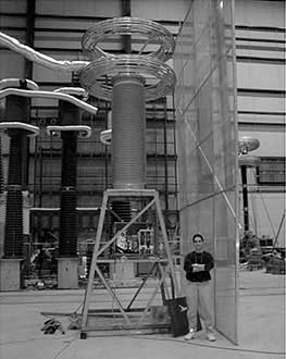
Figure 1
In one test (See Figure 1) the ground plane was located ~1.5m from the center of the column and ~50cm from the corona ring at the top of the NXVT column. The NXVT was energized to 170kV rms (line-to-ground), which represents ~120% of rated voltage. Table 1 shows the results of the electric fields measured by each electric field sensor at its respective location as well as the voltage output of the NXVT as compared to the reference standard cap. The values are given in percent of their respective values when the ground mesh was not present. Even though the electric field distribution is severely disturbed by as much as 20%, the change in the voltage measured by the NXVT is less than 1%.
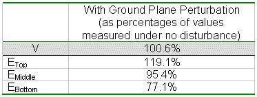
Table 1: Measured values of voltage and electric fields under a severe field disturbance as compared to the respective values under no disturbance. Test accuracy was ~1%.
Rain and water flow may also affect the field distribution around a HV line. Figure 2 shows the test set up at Powertech Labs for examining the effects of rain on the accuracy of the NXVT. Table 2 includes the results of the measurements using both ANSI/IEEE and IEC water flow (rain) specifications. It also shows the results of measurements when the column was wet but no rain was simulated.
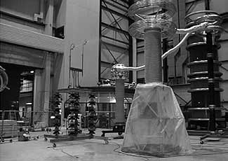
Figure 2
As demonstrated in Table 2, the presence of water caused no significant changes in the calibration (within the accuracy of the measurements), mainly because there were minimal effects on the electric field distribution as compared to a dry condition.

Table 2: Measured values of voltage and electric fields by an NXVT under water/rain related disturbances as compared to the respective values under no disturbance. Test accuracy was ~1%.
Similar tests were repeated on another NXVT using a thinner column, in June 1999 (See Figure 3). The results were similar to those obtained from the first NXVT, confirming the accuracy is maintained with a range of column diameters.
Subsequent to successful demonstration of the operation of the prototype NXVTs at Powertech Labs in 1999, highly accurate electronics and opto-electronics to be used as integral parts of the NXVT have been developed. Also various parts of the NXVT, including the electric field sensors, have been going through extensive temperature cycling in the past few months. The technology is now ready for field trial.
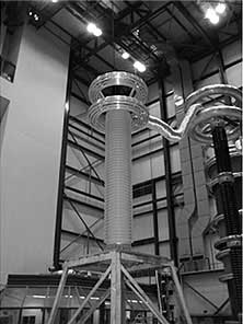
Figure 3
The first field installation of a three-phase, 230kV, 0.3% accuracy class metering NXVT system is scheduled at BC Hydro for April 2000. The voltage sensors actually share the column with the NXCT Optical Current Transducer. The combined unit is know as the NXVCT.
Figure 4 shows a schematic of the field trial installation, which will consist of three NXVCTs mounted on existing support structure within Ingledow substation. Fiber optic cables will connect the sensors to the opto-electronics package remotely located in the control building. The field optics is completely passive for greatest reliability and ease of maintenance.
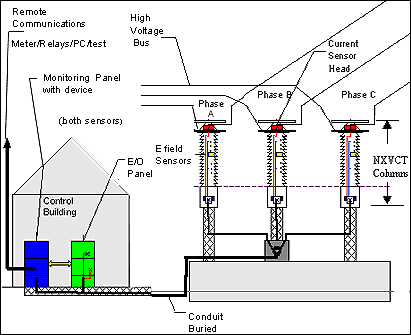
Figure 4
Digital outputs from the sensors will feed a PC based data acquisition system for monitoring of key line parameters, event capture, data logging and remote data access. Low level analog outputs will feed a commercially available power meter. High-energy analog outputs will drive a separate power meter to allow comparison between the two different methods of interfacing with the sensors. An interface to a protective relay is also planned for the project.
A few months of further refinements based on field trial experience will be required before the products are at a state of commercial readiness. NxtPhase expects to launch the product in September 2000.
References
- A.J. Rogers, "Optical technique for measurement of current at high voltage," Proc. IEE, vol. 120, no. 2, pp. 261-267, 1973.
- G.A. Massey, D.C. Erickson, and R.A. Kaldec, "Electromagnetic field components: Their measurement using linear electrooptic and magnetooptic effects," Appl, Opt., vol. 14, no.11, pp. 2712-2719, 1975.
- A.J. Rogers, "Method for Simultaneous Measurement of Current and Voltage on High-Voltage Lines Using Optical Techniques," Proc. IEE, vol. 123, no. 10, pp.957-960, 1976.
- R.E. Hebner, R.A. Malewski, E.C. Cassidy, "Optical Methods of Electrical Measurements at high Voltage Levels," Proc. IEEE, vol. 65, no. 11, pp.1524-1548, 1977.
- D.C. Erickson, "The Use of Fibre Optics for Communications, Measurement and control within High Voltage Substations", IEEE Trans. P.A.S., vol. PAS-99, no. 3, pp. 1057-1063, 1980.
- D.J. Smith, H.W. Dommel, and L. Young, "Integrated optic voltage sensor," Sci. Council British Columbia, Canada, Grant Rep., 1983.
- S. Ihara, T. Mitsui, K. Tada, H. Takimoto, K. Tsujii, Y. Kuhara, M. Tatsumi, Y.Murakami, A. Kawakami, and S. Miyamoto, "The Development of BSO/Fibre-Optic Magnetic Field and Voltage Sensors," Sumitomo Electric Technical Review, no. 23, pp. 179–183, Jan. 1984.
- T. Mitsui, K. Hosoe, H. Usami, and S. Miyamoto, "Development of fibre-optic voltage sensors and magnetic field sensors," IEEE Trans. on Power Delivery, vol. PWRD-2, no. 1, pp. 87–93, Jan. 1987.
- R.F. Cook, "Optical Sensing-metering systems," EEI-AEIC meter & service committee conference, Washington, D.C., pp. 1–4, April 3, 1990.
- T.D. Maffetone and T.M. McClelland, "345 kV substation Measurement system for revenue metering and protective relaying," IEEE/PES 1991 Winter Meeting, New York, pp. 1–8, 1991.
- S. Kobayasi, A. Horide, I. Takagi, M. Higaki, G. Takahashi, E. Mori, and T. Yamagiwa, "Development and field test evaluation of optical current and voltage Transformers for gas insulated switchgear," IEEE Trans. on Power Delivery, vol. 7, No. 2, pp. 815–821, 1992.
- J. Beatty, T. Meyer, and E.A. Ulmer, "Application and Field Trial of High Accuracy Optical Current Transducer for Electrical Power Systems," Conference on Optical Sensing in Utility Applications, San Francisco, CA, May 1991.
- T. Sawa, K. Kurosawa, T. Kaminishi, and T. Yokata, "Development of OpticalInstrument Transformers," IEEE Trans. on Power Delivery, vol. 5, no. 2, pp. 884-891, 1990.
- N.A.F. Jaeger and F. Rahmatian, "Integrated Optics Pockels Cell High-Voltage Sensor," IEEE Trans. on Power Delivery, vol. 10, no. 1, pp. 127-134, Jan. 1995.
- F. Rahmatian and N.A.F. Jaeger, "Frequency Responses of Integrated Optics Pockels Cell High Voltage Sensors," Proc. IEEE/LEOS Annual Meeting, Boston, MA, pp. 462-463, Nov. 16-19, 1992.
Acknowledgement
The authors wish to acknowledge the financial contribution of the British Columbia Advanced Systems Institute and the Natural Sciences and Engineering Research Council of Canada to the project.
Editor's Note: As an Internet community for the power generation industry, Power Online strives to bring you the varied voices and viewpoints of professionals from all facets of this field. Be Our Guest is designed for those interested in writing articles or stating their viewpoints about emerging technologies, innovative project financing strategies, power generation industry trends, or sharing problem-solving case studies. If you'd like to be our guest, please send a brief summary of the article or opinion piece to amurelio@verticalnet.com or call 918-749-2648 so we can discuss your idea. ACM
