Torsional Monitoring of Turbine Generators for Incipient Failure Detection
Introduction
Historically, failures of turbine generator (t/g) rotor components due to torsionally induced high cycle vibration fatigue (retaining rings, shaft cracks, blade root cracks) have been catastrophic and with little warning. Torsional vibration of rotors, the cause of the fatigue, is generally a sporadic, transient phenomenon provoked by sudden load changes on the grid and/or inter-harmonic loading, which lasts from seconds to minutes.
Most of the time these transient events do not overly excite the t/g shaft torsional resonances, but occasionally there is a coincidence of the transient's wave form characteristics and torsional resonances resulting in several cycles of high stress. The accumulation of these cycles may lead to crack initiation and fatigue failure.
In addition, modification the t/g rotor—exciter or turbine replacement, shaft modification may change the torsional resonances into a range of susceptibility.
Very few, if any, machinery vibration monitors are designed for capturing transient, sporadic vibration as is characteristic of the torsional phenomenon. This paper discusses the types of failures, the unique data acquisition requirements and the application of a data acquisition system uniquely designed for testing and monitoring of torsional vibration behavior—Structural Integrity Associate's Transient Torsional Vibration Monitor System (SI-TTVMS).
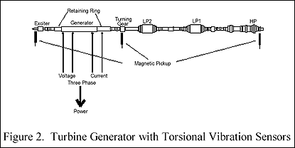
Several power plants have had fatigue cracks on the rotor shaft, in retaining rings and at the turbine blade roots (Figure 2). The failures ranged from cracks found during inspection to complete failures. These failures can cause severe damage to the t/g and are potential human safety problems. The expense of downtime and repair may be in the millions of dollars. The cause of these failures is vibrational fatigue initiated and driven by the t/g rotor torsional vibration.
Retaining Ring Failure
This author is familiar with two retaining rings from two uniquely different turbine/generators having torsionally induced fatigue cracks. One of the rings catastrophically failed, and the other was found in the early stages of cracking by NDE inspection. Unlike previous failures of 18Mn-5Cr rings, there was no evidence of inter-granular stress corrosion cracking. The cracks initiated at the shrink-fit area of the rotor/ring assembly. Metallurgical investigation showed the initiation of the crack was by fretting and that propagation was entirely by high cycle fatigue. Detailed stress and fracture mechanics analysis showed the cause of the fretting and high cycle fatigue was torsion stresses produced by the acceleration/deceleration of the ring relative to the rotor.
Both turbine/generators were near steel mills with high power arc furnaces. In the catastrophic failure case the close proximity of a steel mill with arc furnaces and the relative isolation of the t/g station from other generating stations on the grid resulted in very large and rapid power changes. The steel mill installed Static Var Flicker Control, which under certain operation conditions, led to unstable, super-synchronous, inter-harmonic power oscillations that excited super-synchronous torsional modes of the t/g rotor near 120Hz. The metallurgical fracture mechanics and test data showed that the crack initiation and growth required nearly six months to fail due to the sporadic nature of the forcing excitation.
Shaft Crack
Another type of torsionally induced vibration fatigue problem is shaft cracking. The same plant with the retaining ring failure eight years prior suffered high cycle fatigue shaft cracks in the LP2-Gen coupling. The cracks were suspected of being induced by the sub-synchronous torsional vibration modes (11 and 22Hz). Operational testing indicated significant vibration and stresses at those frequencies related to the steel mill operation.
Low Pressure Turbine Blade Torsional Resonance
Low-pressure turbine blades have experienced failures due to super-synchronous rotor torsional vibration near 120Hz. Turbine/generator rotors have been known to have several torsional modes near that frequency. The concern is coincidence of blade resonance near the shaft resonance. Testing has shown that unbalanced power in the three phases can excite these rotor modes.
Torsional Vibration
Major components of the t/g are on High Pressure (HP), two Low Pressure (LP) turbines, generator and exciter. All rotate on a single shaft supported by bearings at typically 11 locations depending on the number of turbines. Turbine/generators typically run at 1800 and 3600 rpm in the United States and 1500 and 3000 rpm overseas.
Energy produced by the boiler is converted to rotational motion of the shaft through the turbines that drive the generator rotor. The rotor windings, with excitation from the exciter, create current flow through the three-phase generator stator windings. The stator is connected to the grid through transformers and such. The generator mass and the grid load coupled through the stator to the rotor create a torsional resistance to the turbine driven shaft's rotational motion. Ideally and under steady state conditions (constant rotational speed and constant electrical load), the torque remains essentially constant.
(Figure 3) is a simplified model of the t/g system. The model provides a means to discuss the relationship of the shaft excitation forces (input to model) to the shaft torsional vibration response. The mathematical relationship for the ratio of the output to the input is called the transfer function. The transfer function is basically the differential equation that defines the shaft dynamics and can be derived both in the time domain or the frequency domain. The transfer function is dependent on the shaft's mass, stiffness and damping. These parameters define the free torsional vibration modal characteristics—resonant frequencies and associated mode shape.
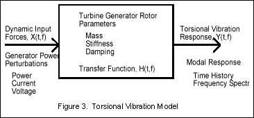
With the shaft transfer function known, for a particular input excitation, the output can be predicted and vice-versa. For our purpose, the model provides a graphic description of the measurements necessary for torsional vibration monitoring and testing. Thus the information necessary to understand the torsional response of the system are the forcing function and the vibration response. The forcing function, power perturbations, can be determined from instantaneous stator output power, with further definition available by measuring the instantaneous stator current and voltage (three phase).
The transfer function can be determined through t/g induced phase imbalance, ramp tests and during normal operation from the broadband frequency, low amplitude normal grid fluctuations.
Forcing Function
Two types of changes in the t/g system can cause torsional variation: (a) turbine perturbations and (b) electrical grid perturbations. The electrical perturbations are due to sudden changes on the grid such as motor starts and arc furnace operation. In general, there are always relatively small perturbations that create a sort of broadband background noise, but with large equipment such as arc furnaces, the perturbations may be in the order of 20 to 100 MW with similar Var changes. These transients may cause phase imbalance and negative sequence currents.
All the sources of perturbations have time, frequency and amplitude characteristics that will uniquely affect the shaft rotation and manifest as torsional vibration. Fast transients will excite higher vibration modes, and negative sequence currents will cause excitation forces near 120Hz. Inter-harmonic currents may cause excitation at any frequency, not just the harmonics. The coincidence of any of these transient forces with a torsional resonance will increase vibration amplitudes significantly.
The torsional forcing functions can have both a pseudo-steady state and transient characteristics where the power amplitude changes over many seconds (large motor starts, grid frequency) to relatively instantaneous changes (several milliseconds) for furnace arcing and line faults. The effect of the speed of power change (rise time) or the frequency composition of the perturbation will determine the amplitude and frequency of the response.
The number of occurrences and the length of time they last for the various forcing functions will determine the fatigue usage of the shaft components vulnerable to this type of failure. The retaining ring failure was calculated to take about six months due to the sporadic nature of the excitation, which would take from seconds to minutes.
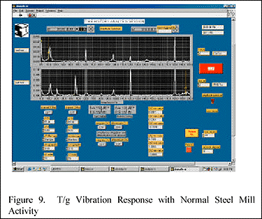
A single unit, 650 MW plant near a steel mill, with the SI-TTVMS installed produced the following resonant responses (Figure 9) as three locations (HP-end, turning gear, exciter-end) due to normal steel mill operation. The torsional modes excited were compared to the calculated mode shapes and frequencies in Table 1 to show the accuracy of the analytical model and to assist in which frequencies to monitor.
Data Acquisition
Most rotating equipment monitoring is based on the premise that the system changes and remains in that state until it either gets worse or is fixed. Consequently, the monitoring system establishes an alarm point at a level, which if exceeded, a plant response must follow. The typical rotating machinery data monitoring systems looks at the numerous data channels sequentially resting at each channel for a period of time to establish a health indicator or graph such as the root-mean-square, peak or frequency spectrum of the rotor displacement. By the time the system has reviewed all the channels several minutes have gone by between monitoring of a particular channel. For most of the t/g vibration problems that are related to transverse rotor motion, the vibration is steady state and continuous, so the "dead" time between channel monitoring is not critical.
Torsional failures, on the other hand, due to their transient nature require high speed, continuous monitoring (no "dead" time) and special alarm algorithms that minimize the false alarms due to electrical transients in the system. A high-speed, PC-based continuous transient torsional vibration monitor (SI-TTVMS) has been developed by Structural Integrity Associates and implemented at several fossil fuel plants to meet these exacting requirements. This type of monitoring should be applied for turbine/generators that are near large transient equipment to measure baseline torsional modal characteristics and after modifications to the rotor are made, which may alter the torsional resonances.
Measurements
The measurements necessary for torsional monitoring and testing of turbine/generators are torsional vibration sensors, stator current, stator voltage and stator power. All measurements must be instantaneous. That is, the measurements received for recording and analysis must not be averaged, but must be able to provide instantaneous time history over a bandwidth of about 5 to 400Hz, depending on the modal characteristics of the machine.
Sensors
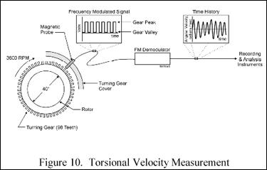
Angular velocity, a measure of the rotor's torsional vibration, is measured, if possible, at three locations. The location of the torsional velocity sensors are based on a combination of parameters: (a) accessibility to the shaft and/or gear, (b) existing sensors that can duplicate as torsional velocity (speed control, shaft speed, for example), and (c) locations which provide modal response. Torsional vibration can be measured with magnetic sensors at gear teeth such as the turning gear, optically with a light reflecting band on the shaft and with strain gages and telemetry.
The use of non-contacting, magnetic pickups directed at the tooth end of precision gears as portrayed in (Figure 10) are the most economical and easiest to use. The magnetic transducer measures the change in magnetic fields due to the sequential passing of the crown and root of the gear teeth and produces a voltage proportional to the magnetic field change. The magnetic transducers can measure over a range of 0.005 to over 5 radians/second, which provides sufficient range and resolution for most phenomenon of interest.
The stator power can be measured using a three-phase, three-wire, unfiltered hall effect transducer connected to appropriate CT and PT circuits and generating a voltage proportional to power. The stator current and voltage of each phase can be measured from plant CTs and PTs using off-the-shelf transducers.
Transient Torsional Vibration Monitor and Test System Description
The SI-TTVMS is a PC-Pentium II based high speed, digital data acquisition system running in the Microsoft Windows 98 operating system (Figure 11). For a two t/g station, the system will typically require 16 channels of analog, dynamic signals composed of six torsional vibration, three generator voltages, three generator current, two instantaneous generator output power, and two spare channels adaptable for tie-ins with other plant process and vibration signals. The system provides relay outputs for warning and alarm indications. The alarm status, sensor amplitude and trend for each channel is displayed on the color monitor when in the monitoring mode. During monitoring, any two channels may be viewed real time as time history or frequency spectrum.
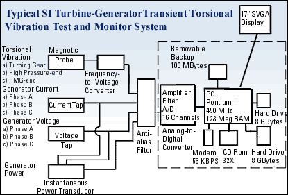
The sixteen analog input channels are passed into the 16-channel analog-to-digital converter (ADC), where each channel is low passed (anti-alias) filtered, amplified and simultaneously digitized at rates up to 6,000 samples per second (sps) per channel. The ADC is a single card installed in the PCI bus on the motherboard.
Digitized data from the ADC is double buffered in the PC memory (RAM) and recorded directly to disk in both the test (manual controlled) and monitor (automatic alarm trigger) modes. The double buffer allows for simultaneous acquisition and data processing while maintaining continuous, seamless data acquisition and storage at the fastest data throughput rates of the ADC. Data are stored on disk in a binary format to minimize data storage capacity. Each file is time and date stamped and provided with a unique, updated file name.
The data acquisition hardware is controlled by National Instrument's Labview graphical interface software, which provides "virtual instruments" to acquire, real-time process, analyze, and store high-speed digital data. The Labview software is a proven, 12-year-old technology that is well integrated with National Instrument's hardware. The combination of National Instrument's Labview software and data acquisition hardware is used throughout the world to provide flexible, high-speed, reliable monitoring and testing.
Continuous Monitor Operation Mode
In the SI-TTVMS monitoring mode, each alarm channel is set up to provide two alarm states—warning and alarm—for each of the four user defined frequency bands. The frequency bands can be continuously set from narrow (1Hz) to broad (one-half the sample rate). Typically, the bands are set for torsional monitoring from 0 to 60Hz to observe the lower sub-synchronous torsional modes, 60 to 120Hz to observe the super-synchronous modes, 120 to 180Hz for the highest torsional modes of interest, and a narrow band to cover a selected mode of interest.
For each alarm channel and each frequency band, two alarm state amplitude settings are user defined—warning and alarm. An adjustable warning/alarm algorithm is established based on number of peaks exceeding the set-point per unit time in order to eliminate false alarms. If the set points are exceeded, the alarm level is triggered, resulting in a display indication and/or an output relay closure and/or an output logic signal sent for external alarm. The time and date for each alarm state excursion is maintained in the monitor mode session data file described below. For each alarm channel frequency band, a count of the number of signal peaks exceeding the alarm set point is maintained in a data file. These values can be used for fatigue calculations, if necessary.
Upon obtaining an alarm state, all input channels are simultaneously recorded to disk for a user-defined period of time in a pre-trigger mode. A historical amplitude trend of the alarm channels is maintained and is dispalayed without interrupting the monitor mode. The trend displays the peak value for each frequency band as described above. Periodically, at the user-defined intervals, all input channels will be automatically acquired similar to the transient recording for an alarm excursion described above. The recording will provide a detailed view of the torsional vibration state at regular intervals.
All pertinent setup information, such as sample rate, engineering unit conversions, alarm points, frequency bands, are stored in a text file attached to each monitoring session. The system automatically shuts down and starts up if the t/g is off line. Also, if a torsional sensor becomes non-operational, the channel will be automatically removed from the system until repaired, while all other channels and systems remain operational.
Transient Recording (Test Mode)
The transient recording mode of operation is used for the automatic alarm triggering in the monitor mode and for manual operation during special testing. The transient recording mode allows for the manual and automatic initiation of the acquisition of data. Data may be acquired in a pre-trigger mode. This allows for collection of data prior to the manual or automatic start-of-collection trigger with the delay set from 0 to 50% of the total data collection time. The pre-trigger mode uses the FIFO circular data buffer concept to allow for capture of data prior to a trigger and is useful in establishing the initial vibration conditions prior to a transient event.
Data are acquired simultaneously for one to 16 channels at rates up to 6000 sps per channel. During transient recording any two channels may be monitored real time as time history or frquency spectrum.
Data Analysis
All data analysis with the SI-TTVMS is performed with the flexible, high-speed Labview Advanced analysis software. The software allows for real time or off line analysis of one or more channels selected by the user.
SI-TTVMS provides the following analysis for the selected channels: (a) Time history; (b) peak detection; (c) root-mean-square (rms); (d) digital filter: low pass, high pass, band pass, two to 10 poles; (e) frequency spectrum using the FFT with outputs in power, rms, peak, power density, rms density; (f) two channel analysis: power spectrum density, cross spectrum, transfer function, coherence and provides the real/imaginary or magnitude/phase graphs (two selected channels only); (g) waterfall displays of time history (two selected channels only); (h) Orbit plots (two selected channels only; (i) integration, single and double of any recorded signal (two selected channels only); and (j) differentiation, single or double of any recorded signal (two selected channels only).
Conclusion
Turbine generator rotor failures due to torsional induced vibration fatigue may be catastrophic and costly. The relatively long length of time from onset of the torsional mechanism to failure allows the opportunity to detect, analyze and safely shut down the t/g. This incipient failure detection is possible with adquately designed data acquisition monitoring systems, such as SI-TTVMS. Applied either as a continuous or periodic monitor, transient, sporadic torsional vibration indications, which differ from the baseline, can be recognized.
References
- "Retaining Ring Failure at Comanche Unit 2, Root Cause Analysis," prepared for EPRI by Structural Integrity Associates, EPRI TR-106640, July 1996.
- "Tosional Vibration Induced Retaining Ring Crack at a Fossil Utility," prepared for EPRI by Structural Integrity Associates, to be issued in Fall 1999.
(Editor's Note: The authors prepared this case study for the Sixth EPRI Steam Turbine/Generator Workshop in August. It is being shared with Power Online readers with Structural Integrity's permission. Not all the graphic elements have been recreated here. Please visit the Structural Integrity Associates Website—www.structint.com—for a of the case study with all illustrations available.)
